News Update - July 2023
Engineering notes
By Tony Massau
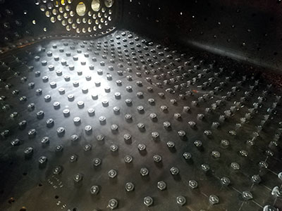
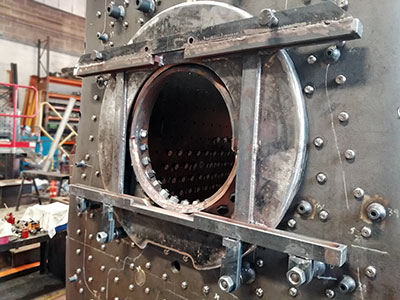
A large proportion of the firebox side stays are now fitted with the nuts screwed on to the protruding ends in the inner firebox. The framework for the fire doors has been trial fitted on to the support studs on the backhead.
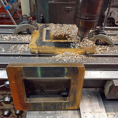
The balance pipe between the two water tanks has been fabricated. It is in several sections roughly following a route from the bottom ends of each tank towards the coal bunker then turning across under the cab floor. The sections are bolted together with flanged joints.
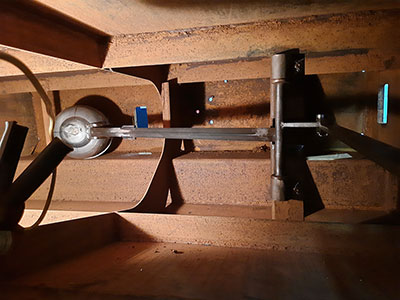
Whilst the right hand water tank has been lying on the ground the ball float mechanism has been installed. Although most of the main bits were ready well in advance this was not the simplest of jobs as a bearing arrangement had to be fitted to a cross member approximately half way down inside the tank. There is a manhole above the area concerned through which in theory a slim person could fit, but to work inside the tank would involve the safety aspect of working in a confined space. However with the tank lying on its side on the floor it was just possible with a bit of ingenuity for a person to lie on the floor and reach in to the appropriate cross member in the tank without gaining any further access. With the tank on the floor some painting has been done to areas difficult or impossible to do with the tank in situ on the loco.
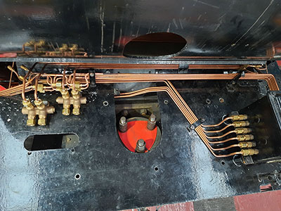
Some additional connectors have been installed into the lubrication pipework and work proceeds on the drive arrangement for the mechanical lubricators.
Machining continues on the carriage warming pressure reducing valve.
Inside inner firebox showing nuts fitted to side stays. Photo: Peter Line.
Firehole door frame trial fit. Photo: Peter Line.
Flanges being machined for the balance pipe between the water tanks. Photo: John Pagett.
Ball float mechanism inside right hand water tank. Photo: John Pagett.
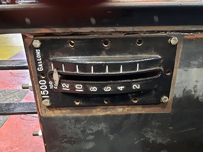
Water level in the tanks indicator. Photo: John Pagett.
Lubrication pipe layout. Photo: John Pagett.
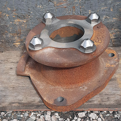
Blast pipe casting. Photo: John Pagett.
